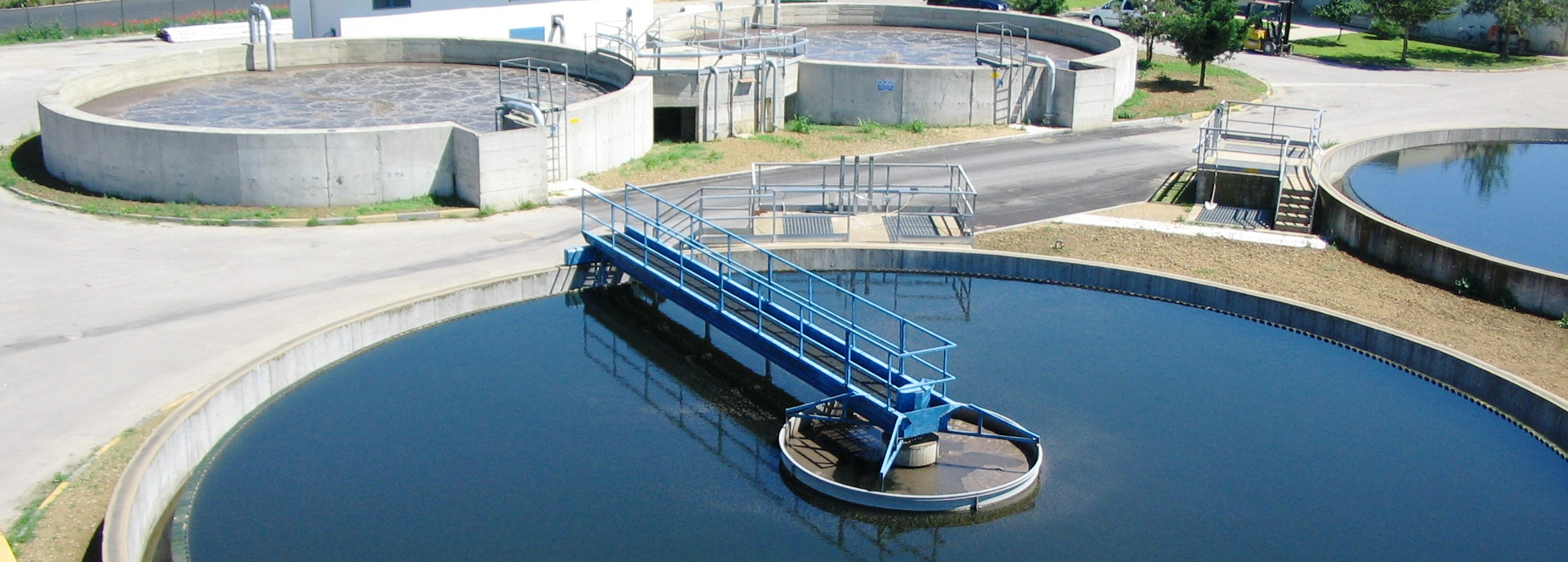
Green Europe Italiana S.r.l. is a company related to water treatment: it accomplishes analytical surveys, offers global service, consulting assistance about engineering, waste management, disposal and it offers solutions tailored for all necessities.
Green Europe Italiana S.r.l. is active since 2013 as associate company of the international group Green Chemicals LTD working in 17 countries among Europe, Middle East and South America. Originally involved in production and application of chemicals for water treatment, today Green Europe Italiana advances solutions from plants, to global service managment, to consulting for any problem related to water. The company gathered a team with decennial expertise in those areas that Green Europe Italiana covers with its activity.
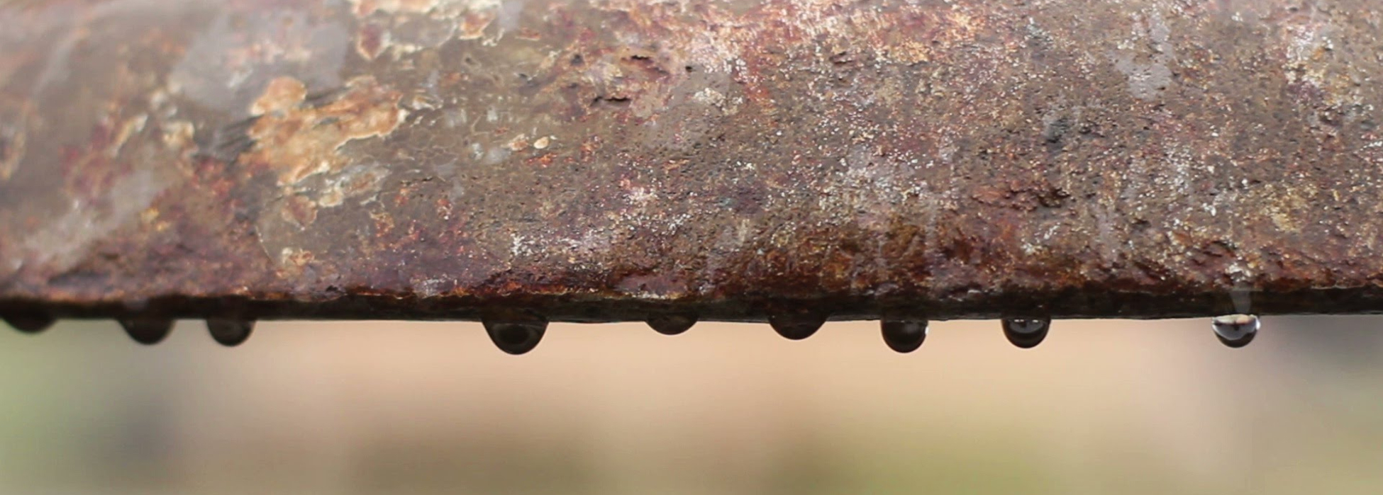
Our services revolve around five areas: consulting and analyses, water reuse, water utilities treatment, industrial wastewater treatment, domestic water treatment. Green Europe Italiana and the associated company Green Europe Service will accomplish jointly those services.

Particular attention in Green Europe Italiana's activity is devoted to assistance following the purchase. Among the services, it is of great interest the mobile laboratory that allows to accomplish in situ control for those situations that require particular attention, as well as the technical-operative framework that performs ordinary or extra maintenance. Green Europe Italiana together with Green Europe Service will do both this assistance.

Decontamination of a washing vessel with hydrocarbon sludge at the bottom and in presence of H2S2, mercaptans, sulfurs, ammonium.

Report and cost analyis for the treatment of CER 01.05.07 waste-drilling mus by Eni's well M.Enoc 10

Efficiency assessment of a chemical treatment of CONA, STOGIT and IREOS waste with on line dosing while disposing the waste from the tanks.
Solution to the issues related to potabilization of the water directed to an Office building of a Plant for special waste collection and treatment
Revamping and management of a wastewater treatment system in a pharmaceutical plant due to a fall in its depurative performance
Control units, Solenoid valves, Manometers, Junctions, Flowmeter, Rotary pump, Membranes, Fiberglass vessels
Ion exchange resins, Filter media, Chemicals: Flocculants, Coagulants, Solution for pH control, Antifoaming chemicals, Antiscaling chemicals, Microbiocides, Chemicals for odour control, Chemicals for membrane cleaning
Microfiltration - Vessels - Filters - Nanofiltration - Vessels - Filters - Ultrafiltration - Vessel - Membranes - Regenerating solutions - MBR
Dosing pumps - Suction pumps - Centrifugal pumps - Tanks - Agitators - Pulse counters - Dosing systems - Probes
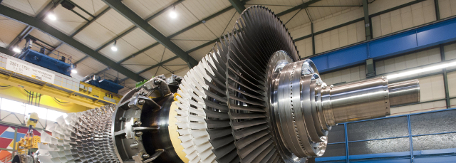
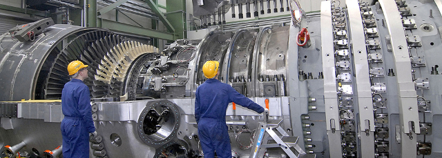
Green Europe Italiana offers plants and turbines. Click on the selection below to know more or contact us.

Administrator
fbottura [at] greeneuropeitaliana [dot] it

Administrative director
gioscerrato [at] greeneuropeitaliana [dot] it
Technical Manager
vpacifico [at] greeneuropeitaliana [dot] it

Technical Sales
mbresciani [at] greeneuropeitaliana [dot] it

Responsible for the website
sbscardina [at] greeneuropeitaliana [dot] it
Technician for industrial plants
Decontamination of a washing vessel with hydrocarbon sludge at the bottom and in presence of H2S2, mercaptans, sulfurs, ammonium.
A vessel for storage of residuals from gas washing at an ENI refinery was seriously contaminated by pollutants that generated an irritating strong smell. That smell was so disturbing that the technical staff of the refinery was prevented from accomplishing the periodical maintenance of the machinery, therefore causing loss in the production.
At a preliminary inspection, persistent deposits of hydrocarbon sludge formed at bottom of the vessel MV 2201 and in presence of H2S2, mercaptans, sulfurs, ammonium adsorbed to its walls. These deposits still remained although the container had been already reclamated by flushing with N2 and hydrodynmic cleaning in streaming and downstream modes.
The aim of the treatment was to remove all the residuals responsible for the smell, like mercaptans, and that were still adsorbed on the vessel walls. The action was articulated in four stages: filling and heating, feeding WET-Treat GE Clean 2000 at the head and bottom of the system, conditioning, and finishing.
In elaborating the procedure, it was necessary to adapt the process to the internal geometry of the vessel. In fact, it didn't allow an optimal flux distribution during the liquid recirculation and as a consequence, the parts that could be reached were limited to the higher side of the vessel. Also, operating in medium pressure steam would have allowed to arrive at higher temperatures and have a more efficient transport of the chemical, increasing much the performances, but it wasn't possible.
The overall scheme for the process is represented in visual form in the process diagram below.
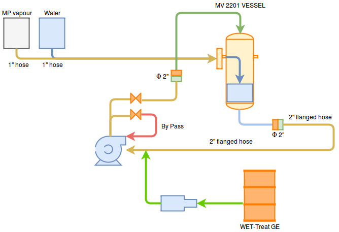
Chart of the sequence diagram for the treatment
The four phases of the treatment will be in the operating procedure articulated in the fourteen points below:
The bottom of the vessel was filled with process water until 25% of the whole volume by a 1” hose. In order to heat, low-pressure steam was bubbled at its bottom at the temperature of 60°C.
The WET-Treat GE Clean 2000 chemical treatment was added to the vessel with a centrifugal pump set on the 7% of the volume of the water within (2.600 kg). Then, the water was recirculated between the drainage lines and the head of the vessel with a volumetric pump processing 150 m3/h. This phase was directed to remove from inside all possible solid deposits or sludge thanks to the surfactant action of the chemical.
After 4 hours, the recirculation of the solution was interrupted and the central opening was sealed, then the solution temperature was raised at 70°C by the hose that was flushing bubbling steam.
It was possible to condition the whole volume by employing the mechanical and thermal effect of the steam. That operation created the best circumstances to maximize the oxydising action of the chemical. that's a saturated fog at a temperature comprised between 60° and 80° degrees, on the sulfur compounds adsorbed on the vessel walls.
The goal was to benefit the features of WET-Treat GE Clean 2000, that is very active in the gas and phase and in aerosol.
After about 12 hours of streaming and having ensured mercaptan absence in the machinery, the washing solution was drained to the system for refinery water treatment. It was then all washed and aired at environmental atmosphere through drainage lines, vessel head and central PDU.
At least, a solution of water and GE DEO V at 10% was vaporised. That product combined the technical features of WET-Treat GE Clean 2000 with an effective covering power.
The treatment described resulted in a very effective removal from the top to the bottom of the vessel of all the residual sulfurous matter responsible for the smell.
Report and cost analysis for the treatment of CER 01.05.07 waste-drilling mus by Eni's well M.Enoc 10
The drilling mus was extracted from a M.Enoc 10 well at Viggiano (PZ). The mud contained baryte and metals coming from the cleaning operations of the concrete tanks. It was necessary to find the best process capable of removing those pollutants from the water whilst satisfying those requirements:
The treatment was chosed through laboratory tests with the goal of selecting the appropriate chemicals feed - in terms of typology and amount - that was able to perform satisfying coagulation and flocculation. Then, the treated mud was further processed with centrifugation and filter-pressing to separate the water from the sludge. At least, the predictive overall costs of the chosen solution were calculated to compare the cheapness in the proposed solution against the starting costs.
The tests were accomplished in four stages: pre-screening, choice of the doses, comparative assessment, final considerations. Each stage is explained as follows:
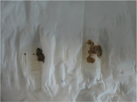
During this stage, some possible treatments for the muds were tested to choose the proper chemical to feed. Four samples of mud (200 mL each) were taken anche the following chemicals were added to each:
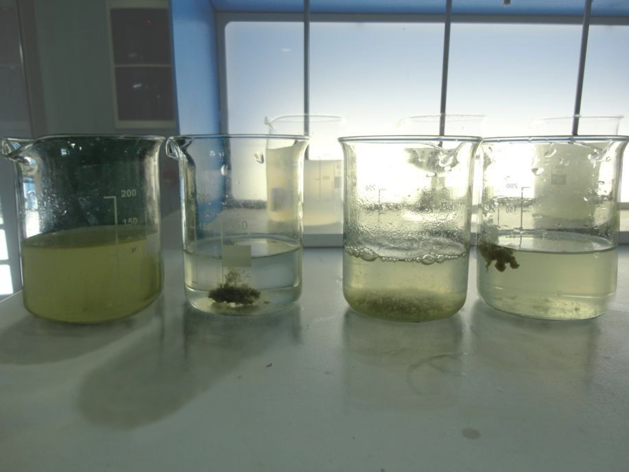
From left to right: 1) untreated water, 2) water and polyamine + anionic polyelectrolite mixture, 3) water and polyamine + cationic polyelectrolyte mixture, 4) water and cationic polyelectrolyte.
During this stage, the sludge was treated with increasing doses of chemicals in order to assess the optimum. The limit dosages are the following:
Considered the SST concentration of the sample (1-2%), the sludge already trated with the chemicals was then sujected to centrifugation and filter-pressing. Four samples were prepared for the purpose:
Process duration: 15 mins
Rpm centrifugation: 2400
The sample prepared for the centrifugation had an original mass of 100g. After the process, the following data are given:
| Sample |
Chemical | Doses (ppm) |
Sludge produced (%) |
Water clarified (%) |
SST water clarified (ppm) |
|---|---|---|---|---|---|
| a | Untreated |
- | 0 |
100 | 2000 |
| b | WCT 1517 + WCT A 40 |
100 + 100 | 6 | 94 | 18 |
| c | Polyamines + Cationic polyelectrolyte | 100 + 100 | 3 | 97 | 287 |
| d | WCT BD 7080 |
100 | 5 | 95 | 31 |
Table with the SST data for the four samples treated with centrifugation
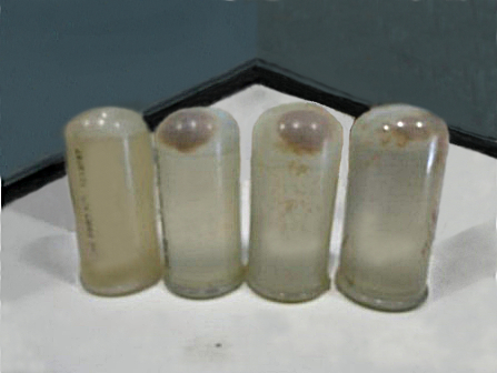
Centrifuged product of the four samples
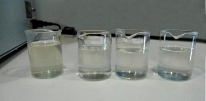
Clarified water collected from the four samples treated with centrifugation
The simulated filtering process was carried out in two stages:
| Sample |
Chemical | Doses (ppm) |
Sludge produced (%) |
Water clarified (%) |
SST water clarified (ppm) |
|---|---|---|---|---|---|
| a | Untreated |
- | 0 |
100 | 2000 |
| b | Polyamines + Anionic polyelectrolyte | 100 + 100 | 6 | 94 | 14 |
| c | Polyamines + Cationic polyelectrolyte | 100 + 100 | 3 | 97 | 302 |
| d | Cationic polyelectrolyte | 100 | 5 | 95 | 35 |
Table with the SST data for the four samples treated with filter-pressing
The vacuum filtering and the filtered product from the process are represented in figures 4 and 5, respectively.
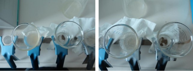
Vacuum filtering of the four samples
Filtered product collected from the 1) anionic polyelectrolyte + polyamide sludge and 2) cationic polyelectrolyte sludge
According to the analyses, the effects of filter-pressing and centrifugation are almost equal since they separated the same amount of water from the mud. Among the tested chemicals, the sample treated with anionic polyelectrolyte + polyamide solution gave the best clarified water in terms of SST. Also, the floc produced was the most stable and homogeneous. In term of the combination of costs and performances, the cationic polyelectrolyte solution at 100 ppm appeared to work best.
In order to assess the overall expense, the costs for:
| SLUDGE TREATMENT |
||||||
|---|---|---|---|---|---|---|
| Chemical |
Sludge inlet |
Chemical doses |
Treatment cost | Sludge outlet (prev) |
Treatment cost/ton | Overall treatment cost |
| PoliFLOC | 1000 Kg |
100 ppm |
0.25 € | 50 Kg |
70 €/ton | 3.5 € |
Table with the overall costs calculated

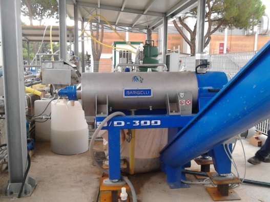
Assessment of the effectiveness for the chemical treatment of the so-called COVA, STOGIT and IREOS waste with dosage in line while boiler-containers are unloading.
Before describing the treatment applied to the industrial plant, it is important to give a brief overview about odour emissions from industrial plants. Industrial odour emissions come from biological system for water treatment and they are represented by reduced catabolites, or sulfur, nitrogen, and carbon compounds that are not completely oxidized. This distasteful smell is often due to very small quantities of matter and the harassment is not always proportional to the toxicological effects they might cause. Althought distasteful smell might induce spontaneous nuisance, like nausea, emesis, headaches or other pains, it is not harmful to human health. Indeed, these effects could be more likely to be related to individual sensory or psicological perception at receptor- or brain level than a disease
A system for industrial odor control was already installed in the area. The original system consisted in an acid/base scrubber treating the gaseous emissions from the biological aeration tanks, and an active-carbon system in dust adsorbing the organic matter responsible for the smell from the process liquid.
The present study was aimed to modify the process by adding appropriate chemicals to the process liquids, hence the treatment goal was to select the best chemicals to feed the wastewater while discharging the tanks.
The product WET-Treat BioTrol 117 was tested as it is highly reactive to H2S, mercaptans, amines and it is capabile to extend its action to muds which follows drying process as well. Also, the product doesn't contain any harmful substance to machineries, processes or people, which fitted perfectly with the purpose.
The methods developed for odor control are classified into two general cathegories:
Two samples of 100 mL each were collected from the two kinds of waste and the chemical 50/100 ppm were injected. After reacting for few seconds, the panel tested the samples and they soon recognized the treated one. Besides, the panel also appointed residual smell as hardly perceptible or absent.
The results are displayed in the table below.
| Sample | Dose WET-Treat Biotrol 117 |
Smell |
|---|---|---|
| COVA - untreated |
- |
Strong-smelling, characteristic Hydrocarbons and sulfur compounds |
| COVA treated | 50 ppm |
Hardly perceptible |
| IREOS - untreated | - | Amines |
| IREOS treated | 50 ppm | None |
| STOGIT - untreated | - | Rotten eggs, very strong (marker) |
| STOGIT treated |
50 ppm | Hardly perceptible |
Table showing the panel results for the odor assessment of untreated water compared against the treated water.
Successively, a a test to check the product effectiveness on treating wastewater or plant was accomplished. A dosing pump was set on 20 L/h injecting until 200 ppm of product, and it was installed in the outlet Water Line. The product was feeded to the flexible exhaust line, at the closest point to the attachment between the tanks by a proper fitting. The pump aspirated the material straight from the 250 Kg-packaging and it was added at 50 ppm to the carrier. In terms of odor perception, the result even clearer than the laboratory stage. The panel verified the odor as "non perceptible" also in this case.
The WET-treat Biotrol 117 was applied to the biological plant and it removed effectively the strong smell.
Solution to the issues related to potabilization of the water directed to an Office building of a Plant for special waste collection and treatment
A Plant for special waste collection and treatment placed in an industrial area in the Central Italy holds an Office building where employers and managers of the company operate. The premises with bathsrooms, showers, and several water facilities had available as service water only well water sanitized with sodium hypochlorite, filtrated and deferrizated. Despite this, the water still didn't meet the requirements to be employed for its purpose. There is below the table reporting the registered values for the water after chlorination and iron removal:
| Parameter | Value | Unit of measure |
|---|---|---|
| Fluorides | 2.7 | ppm |
| Sulphates | 348 | ppm |
| Manganese |
599 | ppb |
| Aluminum | 427 | ppb |
| pH | 6.1 | |
Parameters of the water just after chlorination and iron removal
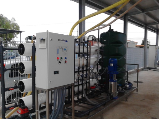
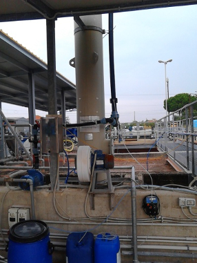
Green Europe Italiana set their activity in installing a complete system for potabilization at the Client's site. Tbe system comprised a Reverse Osmosis unit, a dedicated tank (image 1), an automatic pH control system coupled to an alcaline agent dosing facility (image 2).
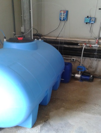
Tank for the water treated with RO storage
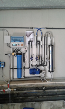
Automatic pH control system and to alcaline agent dosing facility
Besides, a global service contract was stipulated for the installation of all the necessary materials as well as two technical inspections a month, the ordinary and extraordinary maintenance for all the components set by Green Europe Italiana.
The values of the water treated with this procedure are reported in the table below.
| Measure | Conductivity (µS/cm) | Tank pH | Clorides (mg/L) |
Aluminum (mg/L as Al3) |
Iron (mg/L as Fe2) |
Fluorides (mg/L as F) |
Sulphates (mg/L as SO4) |
Manganese (mg/L as Mg) |
Conductivity Permeate RO |
Aerobic Bacteria (Col/mL) |
|---|---|---|---|---|---|---|---|---|---|---|
| 1 | 246 |
6.70 | 46.9 | <0.001 | <0.01 | 0.360 | <0.01 | <0.01 | 21.2 | <100 |
| 2 | 276 | 7.35 | 1.3 | 0.006 | <0.01 | 0.215 | <0.01 | <0.01 | 18.6 | <100 |
| 3 | 239 | 7.30 | 2.5 | <0.001 | <0.01 | 0.321 | <0.01 | <0.01 | 23.1 | <100 |
| 4 | 248 | 7.25 | 3.2 | 0.006 |
<0.01 | 0.276 | <0.01 | <0.01 | 32.1 | <100 |
| 5 | 265 | 7.20 | 8.0 | 0.001 | <0.01 | 0.211 | <0.01 | <0.01 | 29.6 | <100 |
| 6 | 261 | 7.85 | 16.0 | 0.001 | <0.01 | 0.341 | <0.01 | <0.01 | 45.3 | <100 |
| 7 |
289 | 8.11* | 21.0 | <0.001 | <0.01 | 0.251 | <0.01 | <0.01 | 37.2 | <100 |
| 8 | 260 | 7.37 | 17.0 | <0.001 | 0.02 | 0.340 | <0.01 | <0.01 | 53.2 | <100 |
| 9 | 248 | 7.62 | 12.0 | 0.001 | 0.02 | 0.162 | <0.01 | <0.01 | 38.2 |
<100 |
| 10 | 223 | 7.21 |
8.0 | 0.001 | 0.01 | 0.213 | <0.01 | <0.01 | 32.2 | <100 |
| 11 | 249 | 7.85 | 3.7 | 0.0015 | 0.02 | 0.164 | <0.01 | <0.01 | 32.6 | <100 |
| 12 | 229 | 7.28 | 8.0 | 0.005 | 0.01 | 0.003 | <0.01 | <0.01 | 32.2 | <100 |
| 13 | 238 | 7.30 | 17.0 | <0.001 | <0.01 | 0.160 | <0.01 | <0.01 | 31.8 | <100 |
| * 7.2 after cleaning probe |
||||||||||
Measured values of the potabilized water with the new treatment scheme by GEI during the period of six months
It is clear from the data reported above that the values quite satisfy the limits as for the D.Lgs. 31/01 of Italian regulations with respect to the quality fo water destined to human use.
Since the first day of the treatment, the quality of the water has turned out to be compliant with the legal limits imposed for drinkable water. The further monthly check that the technical staff of Green Europe Italiana accomplishes confirm the inspections by the local healthcare company.
Revamping and management of a wastewater treatment system in a pharmaceutical plant due to a fall in its depurative performance
A pharmaceutical plant located in Central Italy had a plant for wastewater treatment that didn't fit its purpose longer since it didn't guarantee the necessary depurative performance over long periods.
The situation came to happen with the analytical and operative check by Green Europe Italiana conducted for a period of six months. Therefore, it turned out that the actual volume of hte oxidation tank was not compatible with the actual hydraulic load nor with the average COD of the inlet (look at Table 1).
| INLET | ||
|---|---|---|
| Parameter |
Value | Unit of measure |
| Wastewater Temperature |
20 | °C |
| Ammonium in | 116 | mg/L |
| BOD in | 2,000 | mg/L |
| Load factor |
0.10 | Kg BOD/Kg SS day |
| Qin | 100 | m3/d |
| MLSS | 4.0 | Kg/m3 |
| Oxygen Concentration |
3.0 | mg/L |
| Security Factor | 1.75 | |
| Cost of Disposal |
100 | Euro/Ton |
| % SS Sludge at Disposal |
1.20 | % |
| N Dose | 450 |
mg/L |
| C Dose | 0 | mg/L |
| OUTLET | ||
|---|---|---|
| Parameter |
Value | Unit of measure |
| DeNitro Tank Theoretical Volume |
276.4 | m3 |
| Oxidation Tank Theoretical Volume | 298.0 | m3 |
| Yield | 0.94 | |
| Qsup |
7.29 | m3 |
| Sludge Recirculation from Ox to DeN | 10.42 | m3/h |
| Expected BOD at Blowdown | 41 | mg/L |
| Sludge Disposed |
887 | T/year |
| Cost of Disposal | 88,703 | Euro/year |
List of inlet (left table) and outlet (right table) values for the system in optimal configuration before the revamping
Another issue encountered was related to the lack of a system for solid-liquid separation for the muds at the final decanter. Indeed, since large quantities of muds that were very low in SS were produced, a scarce sludge removal was performed on the system.
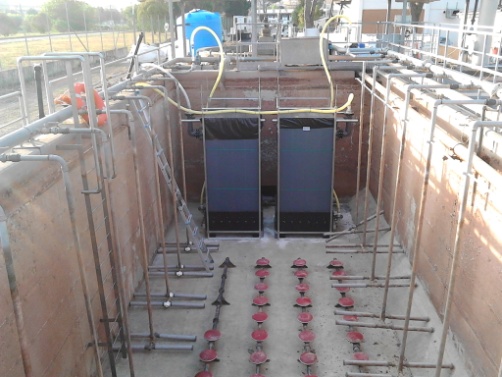
Since it wasn't possible to implement the overall capacipty of the sysyem with civil works, an appointed solution was to increase this capacity by installing MBR membranes. Before doing, Green Europe Italiana tested their suitability installing a MBR pilot plant running in parallel with the exising system. The MBR system was equipped with a membrane 100 square meters wide and it was placed in a 20 foot container. The results of the experiments turned out to be positive, as displayed in Table 2.
| INLET |
||
|---|---|---|
| Parameter |
Value | Unit of measure |
| Wastewater Temperature |
20 |
°C |
| Ammonium in |
116 | mg/L |
| BOD in |
2,000 |
mg/L |
| Nitrates in |
2.50 | mg/L |
| Q in |
100 | m3/d |
| MLSS | 15.0 | Kg/m3 |
| Oxygen Concentration |
3.0 |
mg/L |
| Security Factor |
1.75 | |
| Cost of Disposal |
100 | Euro/Ton |
| % SS Sludge Disposed |
25 | % |
| N Dose |
450 | mg/L |
| C Dose |
0 | mg/L |
| OUTPUT | ||
|---|---|---|
| Parameter |
Value | Unit of measure |
| DeNitro Tank Theoretical Volume | 73.7 | m3 |
| Oxydation Tank Theoretical Volume | 79.5 | m3 |
| Yield | 0.94 | |
| Qsup |
2.13 | m3/d |
| Sludge Recircation from Ox a DeN |
10.42 | m3/h |
| Expected BOD at Blowdown |
41 | mg/L |
| Sludge Disposed |
47 |
T/year |
| Cost of Disposal |
4,665 |
Euro/year |
List of inlet (left table) and outlet (right table) values for the MBR system in optimal configuration
Following the positive result of the MBR pilot system installation, the plant modifications that Green Europe Italiana designed and attended in full were applied the together with the Direction of the site. These adjustments involved the installation of:
The parameters registered returned to normal and the system is running regularly since Aug 2016.

Water can be devoted to several purposes. It can indeed be used as a thermal fluid in cooling systems or in steam production, as a process fluid in several kinds of industries - pulp and paper industries, sugar industries, food industries, etc. -, as a waste or as a municipal water for public and private use. Some situations may require optimization to improve the yield and reduce consequently both operating costs and environmental impact. In addition, should water not be within the limits due to purposes or regulations, it might need threating to satisfy the requirements.
The solution to these problems often needs in-depth knowledge in the field and Green Europe Italiana can help you find the best solution to your problems with its competence and thirty-year expertise of its technicians.
The treatment strategy accomplished is the following:
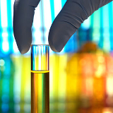
Our analyses are realized by our technicians or in specialialized laboratories holding the following certifications:

The products we use hold the following certifications:


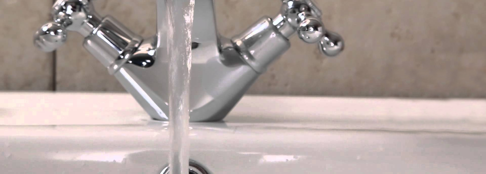
Water is widespread. It it used in household activities, the first of which is personal and environmental care, food or health. It is therefore important for water to be compositionally adequate to satisfy the requirements for such purposes. Among these, there are hardness, microbiological composition and presence of heavy metals.
Hardness is an important parameter for water quality assessment since calcium and magnesium ions at high contents can generate incrustations in the pipes or in other parts of the hydraulic system like faucets or boilers (calcareous deposits). They can also bind the constituents of the liquid detergents to produce low-soluble compounds with a double consequence. By one side, limestone accumulation causes a rise in the energetic bill. On the other side, the detergent power of soap, additives, hair conditioners, fabric softeners or rinse aid for dishwashers goes greatly reduced bringing to serious waste of the economical and environmental sources. The total of this loss is esteemed around 1500 euros a year per family.
All waters are populated by microbacteria, some of which are really dangerous towards animals, like Legionella or Salmonella that are just some of the organisms growing in water bodies. The consequences of this colonization are really hazardous against human health as demonstrated by the incresing number of cases of legionellosis and salmonellosis worldwide so that it should be controlled. An ideal support for bacterial proliferation are the same crusts forming on watersaver attachment, to give a case in point.
Some inorganic compounds that are known as "heavy metals" are also present in waters and are really toxic to healt. They are metallic ions like cadmium, chrome, lead, arsenic, nikel, mercury, aluminium, manganese from natural or anthropic activities. In the first case, they occur as oxides, on the second case as ions coming from a number of industrial processes (metallurgical industry, paints industry, and so forth) generating muds or acting directly on human metabolism.
The issues of above can be avoided installing household systems for water purification. These facilities are small, easy to install and to maintaing, economically and technically speaking.
Green Europe Italiana can make analytical studies on your domestic water to check the main parameters for quality assessment of drinkable water and to find a solution to your needs.
Industrial waters are a good source of water for industries for two main reasons:
In an industrial area water is used as a raw material added to productive activities (process water) or as a fluid for cooling high-temperature systems or production of the steam feeding the production. In addition, water are present in plants as first rain water that get full of ground pollutants by dissolution in the liquid.
Throughout the plant activity, several problems with regard to the life of single components or important variations in the yield can happen to arise.
Considering what stated before, water utilities can be classified into:
depending on the kind of source water is taken from, - acquatic groundwater, well, river, lake, sea, waterwater to reuse - it can have particular compositional features so its preparation/softening/demineralization/purification is tailored for it.
the activities related to first rain water (and sometimes second rain water also) include design, carrying out, implementation of the specific treating systems. In case of systems for first rain water, oiling and coalescence filtration are particularly important, while the overall scheme for second rain water needs studying and organized according to its final destination (look at ZLD plants).
Since industrial waters may be corrosive or act as corrosive agents against some components of the systems in relation to some chemical-physical features (Langelier index), it is common to condition these waters with chemical treatments dedicated to avoid either corrosion or fouling. It is also important to check microbiological growth (biofouling) since it prevents proper thermal exchange and causes corrosion under cover due to deposition on exchange surfaces. Those phenomena appear in both open and closed circuits with evaporative tower. Green Europe Italiana offers chemical treatments specifically studied for each situation.
Depending on the kind of boiler (low, middle, high pressure boiler), increasing purity is required for the inlet. Indeed, should a certain degree of salinity be considered acceptable for low pressure boilers but it is not the same as high pressure boilers, which needs very pure water. A similar criterion is considered for dissolves gases (oxigen and carbonium dioxide).
Our company advances complete and specific programs treatment programs that take in account the features of steam production.
Green Europe Italiana can solve your problems related to water utilities treatment with a variety of solutions including:
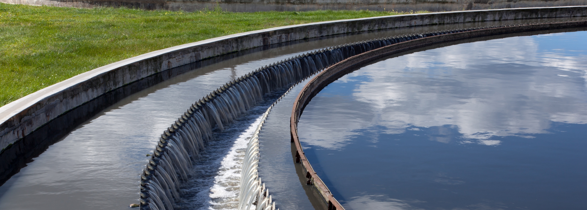
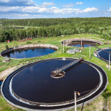
Waste water treament is intended as a series of chemical, physical an biological processes aimed to remove the pollutants from urban and industrial wastewater. Chemical processes are intended for the dissolved fraction in wastewater to treat chemically, physical methods are aimed to remove the suspended solids, and biological treatment has the purpose of separating the solids from the water.
This complex series of operations consists in pretreatment, oxidative-biological, and further treatment. Pretreatment is accomplished to "relieve" water from coarser component as well as SSS (Settleable Suspended Solids) before passing through biological treatment. It consists mostly of grating, sieving, primary sedimentation, flottation (with DAF plants) ans sometimes also oiling (whenever the waters are rich in fatty compounds), and sand separation. The choice for one system rather than another depends heavily upon chemical-physical features of the water to treat.
Then, oxidative-biological treatment is made through microbiological aerobic populations (or anaerobic at limited extents) that attack the SSS escaped from the primary sedimentation together with biodegradable and not biodegradable NSS (non settleable solids). Although microbacteria don't digest non-biodegradable NSS, it is segregated within the biomass and just increase the overall dimension. At the same time biodegradable NSS is processed as metabolites via enzymes. In all cases, biomass generates dense sludge from which water is separated through sedimentation or filtration (MBR membranes). From this point, sludge and water can be treated separately in two lines different lines (water line and sludge line) and each can be treated further.
According to the composition and function they accomplish, water can be further treated with chemical, physical-chemical, biological, natural-biological systems to produce water of better purity. This step includes further removal of remaining SSS, nitrogen, phosphorus compounds, disinfection, an so forth. Finally, sludge can be processed to extract water (centrifugation, for instance) or be recirculated at the head of the oxidative-biological line.
Wastewater treatment is one of the fields where Green Europe Italiana developed particular specialisms and one of the most critical areas as well. In most cases, issues related to treating systems management appear whenever the output changes greatly in positive or in negative since it changes the inlet flow consequently. Also, environmental fluctuations and temperature especially, can affect negatively the performances of those systems in the physical and biological balance of some or many of the dynamic cited before.
The solution to those problems requires wide competence ranging from plant building, engineering, chemistry, and so forth, hence the number of people who hold this expertise is really low. Green Europe Italiana is among this limited number and can:

Green Europe Italiana accomplishes analyses of:
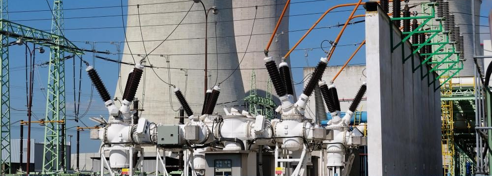
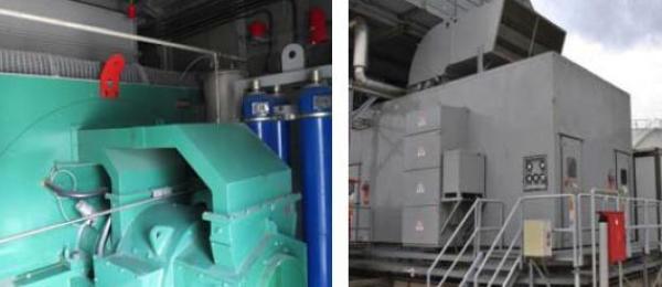
The power plant is in excellent conditions and well-maintained. Currently used as a stand-by power station, it regularly proofs its capability to smoothly run according to its needs. Equipped with an emergency diesel it is capable of black start operation.
The station provides a total installed capacity of 147 MWe, consists of three (3) Gas turbines type GE LM 6000 PC Sprint, 49 MWe each, and by design is offering a significant advantage to the interconnected system, i.e. a very quick start-up reaching its maximum capacity performance in only 20 minutes. The offered scope of supply is all the equipment for a complete plant (turnkey) i.e. from gas supply including gas compressor and reducing station up to the 150 kV SF6 substation and requires no additional equipment to be installed at the new site.
The plant is being sold „as it is and where it is“. In agreement with the seller plant surveys are possible as well as attending trial runs or boroscopic inspections.
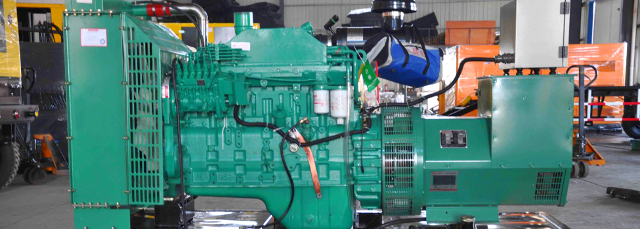
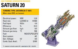
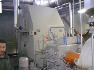
Saturn® gas turbines have proven themselves in over 4800 installations. Introduced in 1960, they have logged more than 620-million operating hours and are available in a single-shaft, constant-speed configuration for driving generators.
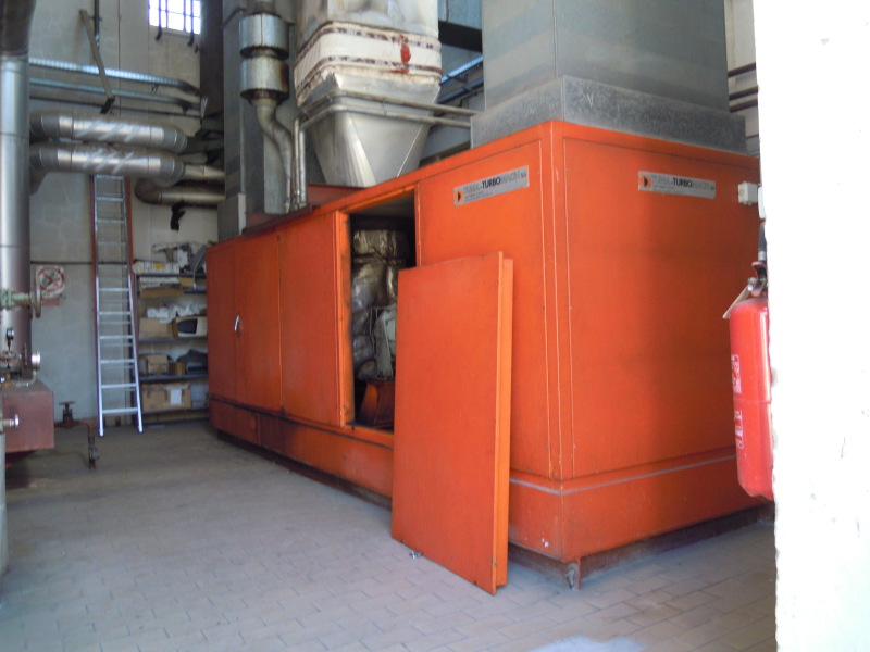
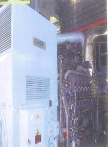
The machine that we have is a Saturn 20 a gas turbine coupled with an alternator AWK 400 V.
The system has had a complete overhaul and actually has about 8300 hours of running.
Plant was built in the south of Sicily (Italy) in 2003, but due to bureaucratic reasons it started very recently.
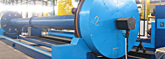
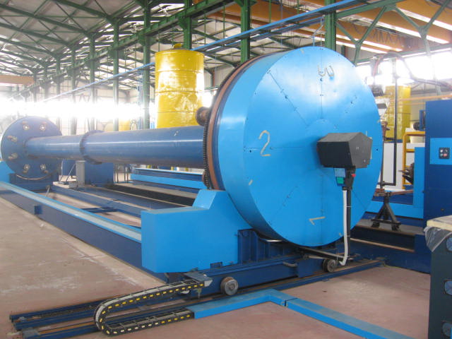
Technology used: a filament winding reciprocal process (discontinuous)
Two complete lines for production of GRP pipes
Length 12.500 mm
Diameter 200 ÷ 3.000 millimeters
Main components:
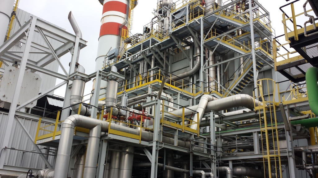
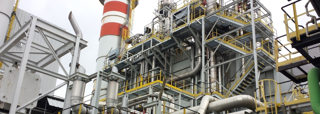
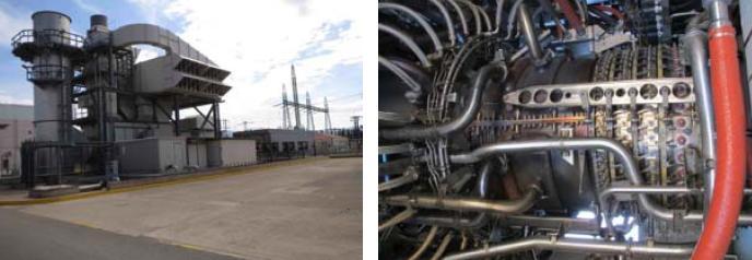
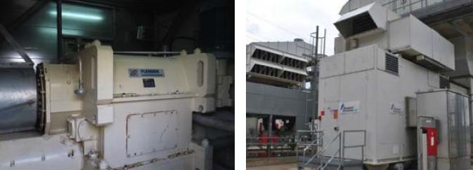
This combined cycle power plant is able to produce electrical power and steam.
It was first synchronized in 1994, entered commercial operation in February 2005 and was finally put in conservation mode in 2010, after the end of the steam purchase agreement with the steam customer.
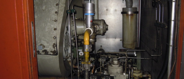
It is mainly composed by:
The Central, in commercial operation since 1994, consists of a group of generation, fueled with natural gas, as follows:
Gas turbine EGT RLM 1600 (G1), electric generator and recovery boiler with production of 19 tons/h of steam at rated load, at a pressure of 40 bar and temperature of 400 ° C.
The group is completed by a condensing steam turbine, fed with steam coming from the boiler of the gas turbine group, and by an air cooled condenser.
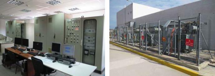
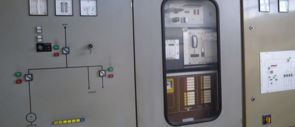
Are also present in the Plant following facilities:
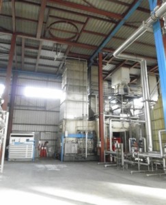
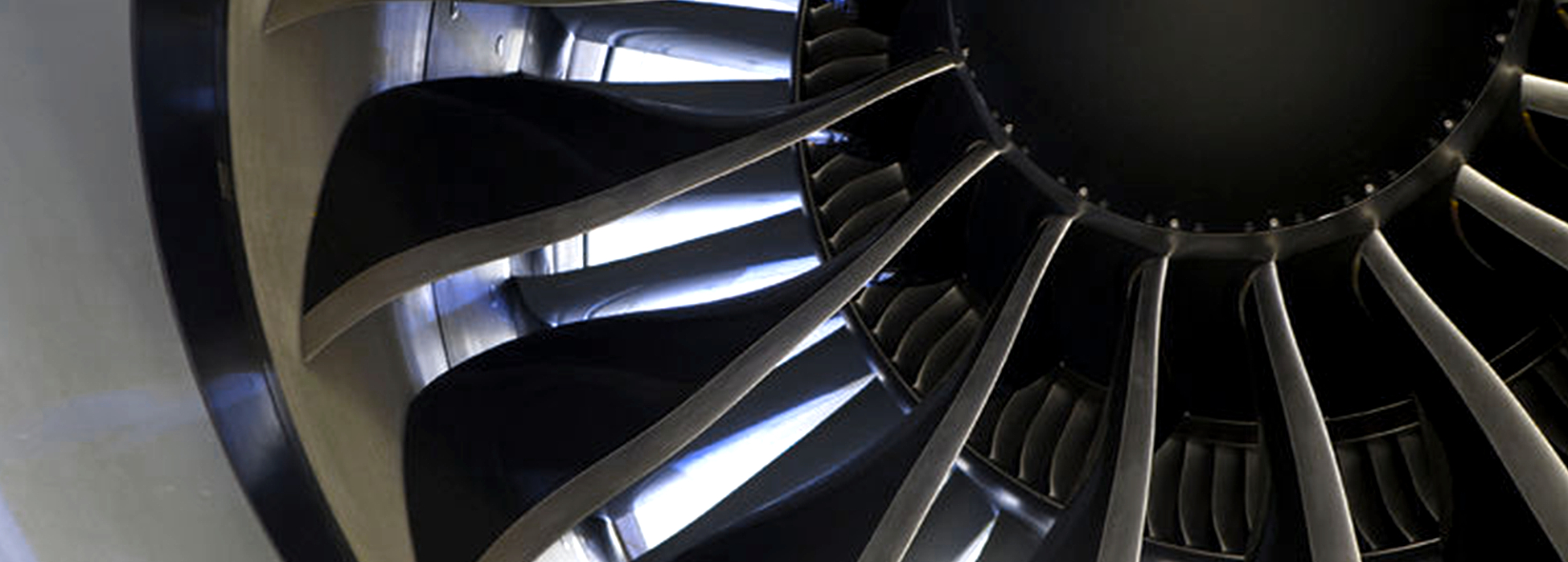
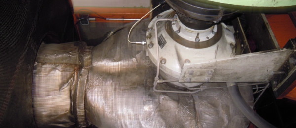
As previously mentioned, the generation group of this Power Plant is composed of a gas turbine EGT RLM 1600 and (G1), electric generator and recovery boiler.
The RLM 1600 turbine is of type dual spool consists of two shafts of which the first associated to the compressor and the high-pressure turbine (HP), while the second format from power turbine to two stages of expansion.
The turbo gas is equipped with a soundproof compartment which entirely covers the turbine, the gearbox and the generator. This compartment, made ??entirely made in carbon steel supports directly on the base of the turbine.
The turbine is powered exclusively by natural gas, with capacity at nominal load to 3,500 Sm3/h, provided at about 40 bar (33/75 bar) from SNAM network.
Inside the combustion chamber, the control of the flame temperature for the primary reduction of oxides of nitrogen products, is obtained by direct injection into combustion chamber of superheated steam (approximately 1,200 kg/year of steam), product in the recovery boiler.
The mechanical energy produced by the turbine is converted into electrical energy, in the form of alternating current, from a three-phase alternator with frequency 50 Hz.
The alternator, with rated power equal to 17500KVA, produces current at 15/20KV that, through the transformer, switch to 130KV.
The fumes produced by combustion of natural gas, after the drive of the turbine, are conveyed to the recovery boiler, able to produce, at rated load, approximately 19 tons/h of steam at a pressure of 40 bar and temperature of 400 ° C.
The boiler is a water tube type with natural circulation. The heat exchange surface is constituted by pipes made ??of carbon steel, in which water flows in countercurrent with combustion smokes.
To increase the efficiency of the boiler a bank of high pressure superheater and an economizer that warms the incoming water before it happens the state transition, are present in the opposite position.
The steam produced flows into the steam turbine for the production of additional energy.
The group is completed by a steam turbine, condensation type, coupled to a synchronous generator 4-pole three-phase type. The steam turbine is he axial type at multistage condensation action with a levy adjusted for the extraction of the feed steam of thermal loads. The extraction adjusted divides the turbine into two sections, AP and BP, whose sizing is designed to optimize the overall performance of the machine.
The flow of steam entering to the turbine, (400 ° C and 41 ATA), is equal to 32.5 tons /h.
At the exit from the turbine, the steam is condensed in an air condenser, for a description of which, reference should be made to a next paragraph.
The make-up water system for the boiler blow down consists of a demineralisation unit and a thermal deaerator, which treats the demineralized water produced.
The water for the DEMI unit treatment is drawn from wells for industrial use; surface water is also available.
Each demineralization line can treat a maximum flow rate of 20 m3/h of water, which reaches at the output a conductivity equal to 0.5 µS/cm and an SiO2 content of 0.05 ppm.
The demineralisation unit is able to produce all demineralized water that Plant needs.
To meet the specific requirements of steam injection into the gas turbine is necessary to perform with two stages of treatment:
The demi water produced is subsequently sent to the deaerator, constituted by a vertical tower of degassing in carbon steel, installed above the tank for collecting the degassed water and with a manhole.
The tower has a diameter of 1,600 mm and a height of about 3 m, was calculated for an hourly capacity of more than 10% to that of operation.
The collection tank of degassed water, it also in carbon steel and equipped with a manhole, has a diameter of 2,200 mm, a length of 10.100 mm and a capacity of 35 m3. The tank is supported by two saddles for supporting the load distribution, one of which acts as a fixed point and a sliding point to allow for expansion.
The deaerator can treat at most 35,000 kg/h of water at a temperature of 110 °C.

The condenser, positioned downstream of the steam turbine, is a vertical beams inclined type, with forced draft, has a heat exchange surface of bare pipe equal to 860 m2, which becomes 20,250 m2 of finned tube.
The steam flow rate varies from 25,000 to 33,000 kg/h at a pressure between 0.2 and 0.36 ATA, while the air temperature used is 21 ° C.
The condenser consists of:
The closed cooling system cools the oil of the steam turbine through a heat exchanger and feeds the circuit of condensation of air conditioners placed in control rooms. The water used circulates in a closed loop circuit and is cooled by air in 2 cooling towers.
The water of the cooling circuit is replenished in the amount evaporated, with water taken from the Chiebbia river and is conditioned with specialty chemicals to prevent the microbiological growth of algae and the formation of scale.
To maintain the salts concentration in the cooling water to acceptable levels is necessary to eliminate a certain amount of water (blow-down or bleed) that is released into the white water network.
The system of protection against gas leaks has been specially developed to be placed inside the compartment of the gas turbine. The system is fully automatic and provides detection, alarm, and phase of extinction of any fire.
The system includes:
The table below shows a summary of the energy performance of the Central under the current set.
| Nominal thermal power (MW) | Electricity to the hearth (on 2007) (MWh) | |
|---|---|---|
| 49,5 | 106.190,6 | |
| Nominal electrical power (MW) |
Output (on 2007) (MWh) | Portion sold to third parties (on 2007) (MWh) |
| 20,5 |
42.476,24 | 40.667,79 |
| Yield (%) |
||
| 40 | ||
In the Table is shown an Electrical nominal power of 20, 5 MW as was also installed in the generation unit, a second gas turbine EGT Typhoon, electric generator and recovery boiler with production of 7.5 tons/h of steam at nominal load, at a pressure of 40 bar and temperature of 400 ° C., today no longer available.
| ID | Descrizione | Locazione |
Condizioni |
|---|---|---|---|
| ITEM 1 |
38 MW Power Barge, 2 x LM 2500 gas turbines, 50 HZ, liquid fuel, 19,000 hours, immediate availability | Asia |
Used |
| ITEM 2 |
Frame 9 FA Combined Cycle Power Plant, 380 mw, complete plant, 50 HZ, natural gas, recently overhauled | Europe |
Used |
| ITEM 3 |
Two Frame 7 FA, 171 MW each, Model 7241, gas fuel, 60 HZ, Low Nox | USA |
New |
| ITEM 4 |
Frame 7 FA, 213 MW, natural gas, 60 Hz, 18000 volt, 2013 year with warranty | USA |
New |
| ITEM 5 |
Two (2) Siemens (701 DU) gas turbines, 50 hz, 125 MW, dual fuel, with warranty, can operate on HFO | Europe | Rebuilt |
| ITEM 6 |
Two (2) Solar Centaur 50 gas turbines, 60 hz, 4.0 MW, gas fuel, Immediate availability, NEW units | USA |
Rebuilt |
| ITEM 7 |
Three (3) LM 6000 PD gas turbines, 60 hz, 44.7 MW, gas fuel, Immediate availability, NEW units | USA | New |
| ITEM 8 |
Siemens SGT5-4000F gas turbine, 270 MW, 50 Hz, gas fuel, 11,000 volt | Europe |
Unused |
| ITEM 9 |
Siemens SGT -400 mobile gas turbine, 12.9 MW, 60 Hz, gas fuel, 12,900 volt |
Europe | Used |
| ITEM 10 |
Frame 9E Model 9161, 1989 Thomassen, 50 Hz, natural gas, dual fuel,available, 115 MW, 60,000 lifetime hours, immediate availability | Europe | Used |
| ITEM 11 |
Two(2) TM 2500 + Mobile generators, 50 or 60 Hz, dual fuel, 30 MW, Immediate availability | USA | New |
| ITEM 12 |
Two (2) Siemens SGT 800 gas turbines, 50 MW, 50 Hz, new with warranty, natural gas | Europe | New |
| ITEM 13 |
GE LM 2500 PE gas turbine, 50 hz, 22.6 MW, gas fuel, rebuilt with warranty | USA | Rebuilt |
| ITEM 13A |
LM 6000 PF Sprint gas turbine, 60 Hz, 42 MW, gas fuel, very low hours, complete plant | USA | Used |
| ITEM 15 |
Two (2) LM 6000 PA Combined Cycle Power Plant, 42MW gas turbines and 8 MW STG, 50 Hz | Europe | Used |
| ITEM 16 |
LM 2500 PK Combined Cycle Power plant, 38 MW, 50 HZ, natural gas, Allen Steam Turbine, 44,000 hours on GT | Europe | Used |
| ITEM 17 |
Two (2) Pratt Mobilpac gas turbines, 25 MW, 50/60 Hz, dual fuel, full warranty, 4-5 month availability |
USA | New |
| ITEM 18 |
Alstom Combined Cycle power plant, 400 MW, 50 Hz, very low hours, complete plant | Europe |
Used |
| ITEM 19 |
48 MW Power Barge, Westinghouse W251B turbine, liquid fuel, can be converted to gas, 50 hz, 30,000 hours | Europe | Used |
| ITEM 20 |
9.2 MW CHP plant, Two (2) Solar Centaur gas turbines, 3800 kw, 50 hz, dual fuel, 1800 kw European steam turbine, complete | Europe | Used |
| ITEM 21 |
LM6000 PD gas turbine, 45 MW, 2000, 50 hz, natural gas fuel, 43,000 hours | Europe |
Used |
| ITEM 22 |
93 MW GE Frame 6 FA gas turbine plant, 88,000 hours, 50 hz, Natural gas, Combined cycle | Europe | Used |
| ITEM 23 |
220 MW Frame 6 Combined Cycle power plant, Four (4) Frame 6 Model 6541,gas turbines, GE 60 mw steam turbine, Dual fuel, 50 hz, 135,000 hours | Europe | Used |
| ITEM 24 |
Siemens SGT6-3000E gas turbine, 121 MW, 60 hz, 13,800 Volt |
Europe | New |
| ITEM 25 |
GE Frame 6 gas turbine, Model 6541, 37.4 MW, 60 Hz, natural gas fuel, 80,000 hours | USA | Used |
| ITEM 26 |
Two (2) Solar T 60 gas turbines, 5670 Kw, 60 hz, 4160 volt, dual fuel, 2013 | USA | New |
| ITEM 27 |
Two (2) GE LM 2500 gas turbines in mobile packages, 60 hz, 1970 older,units but only 6500 hours. 18 mw, can be bought as is or,overhaul/refurbishment available. | Asia |
Used |
| ITEM 28 |
LMS 100 gas turbine, 50 HZ, 100 MW, natural gas | Europe | Unused |
| ITEM 29 |
11 MW, Four (4) Nuovo Pignone PGT-10 gas turbines, 13.8 kVa, 50 hz, Dual fuel, complete, HRSG, steam turbine | Asia | Used |
| ITEM 30 |
49 MW Siemens SST 400 Steam Turbine, 60 Hz, 13,800 Volt | USA | New |
| ITEM 31 |
245 MW Steam Turbine, GE D-11, Outdoor installation, 60 hz, Immediate delivery, 2002 manufacture | USA | Unused |
| ITEM 32 |
150 MW ABB Coal plant, 50 hz, complete plant, installed in 2001 | Asia | Used |
| ITEM 32A |
2013 Siemens SST 300 Steam Turbine, 15 MW, 50 Hz, new and unused | Asia | New |
| ITEM 32B | 36 MW Coal or Biomass plant, Sulzer boiler, Siemens and Kanis steam turbines, 50 hz, 1982 with substantial refurbishment | Europe | Used |
| ITEM 32C | 35 MW GE Steam Turbine and HRSG, Unused, 60 hz, switchgear and building, no boiler but his could be provided | USA | Unused |
| ITEM 32D | 108 MW Complete Coal plant, Hitachi Steam Turbine, Alstom Boiler, 60 Hz, 1991 in operation | USA | Used |
| ITEM 32E | 12 MW Dresser Rand Steam Turbine, 50 Hz, 1999 year | Europe | Used |
| ITEM 32F | 20 MW Steam turbine, Hyundai generator, 50 or 60 hz, 6 month delivery, warranty | USA | New |
| ITEM 32G | 45 MW Ansaldo non condensing steam turbine, 60 Hz, overhauled, less than 50,000 hours | USA | Used |
| ITEM 33 |
13 MW AEG Condensing Extraction Steam Turbine, 50 hz, 1985, 70 hours of actual use | Europe | Used |
| ITEM 34 |
Three (3) Kongberg/Viking gas turbines, 2740 kw each, 50 hz, dual fuel, Never used, 1980 | Asia | Unused |
| ITEM 35 |
Four (4) Frame 5 N, 20 MW, 60 Hz, natural gas, low hours | USA | Used |
| ITEM 36 |
LMA 1500, dual fuel, 10 MW, 60 hz, zero hour overhaul | USA | Rebuilt |
| ITEM 37 |
Solar T70 gas turbine, 50 hz, 6300 v, 7 MW, natural gas, 2000 year, 42,000 hours | Asia | Used |
| ITEM 38 |
Frame 6 Combined cycle plant, 71 MW, 50 Hz, nastural gas, complete plant, 90,000 hours | Europe | Used |
| ITEM 39 |
Seven (7) Caterpillar C-280-16 Diesel generators, 5.2 MW, 50 Hz, Marine,and ABS certification, seawater cooling, skid mounted, 5 year warranty | USA | New |
| ITEM 39A |
Solar T60 gas turbine, 2003, 60 hz, 4160 V, 4300 lifetime hours, natural gas | USA | Used |
| ITEM 39B |
Solar Titan, 2007 year, 15 MW, 60 Hz, 13800 volt, dual fuel, 1200 hours | USA | Unused |
| ITEM 40 |
Solar T70 gas turbine with HRSG, 50 hz, 11,000 v, 7520 kw, natural gas, 15,000 hours | Europe | New |
| ITEM 41 |
Westinghouse 501 (W1101), 91 MW, 50 Hz, dual fuel, 17,000 hours since overhaul | Europe | Used |
| ITEM 42 |
30 MW GE LM 2500 Combined Cycle power plant, 60 hz, 56,000 hours, dual fuel | USA | Used |
| ITEM 43 |
Several Cummins KTA50 diesel generators, skid mounted, 60 hz, 2008 year, 1096 kW | USA | New |
| ITEM 44 |
CAT 3516 B diesel genset, 2000 kw, 60 hz, skid mounted, 300 hours, 2004, 4160 volt | USA | Used |
| ITEM 45 |
Several Caterpillar C15 Mobile diesel generators, 500 kW, 60 or 50 hz, trailerized with fuel tank, less than 400 hours | USA | Used |
| ITEM 46 |
GE LM 6000 PD, 42 mw, 50 Hz, natural gas, complete plant, 50,000 hours | Europe | Used |
| ITEM 47 |
LM 6000 PA Combined cycle power plant, 50 hz, dual fuel, 11,000 volt, 125,000 hours | Europe | Used |
| ITEM 48 |
Two (2) Mars 100 gas turbines, 60 hz, liquid fuel, 2600 hours | USA | Used |
| ITEM 49 |
LM 6000 PC Sprint Combined Cycle, 60 HZ, natural gas, 17,000 hours | USA | Used |
| ITEM 50 |
52 MW Wartsila Multifuel generators, Model 20V34DF, set for natural,gas,or diesel, can be modified for HFO. 50 hz, 8700 kw each, New and,never,installed | Europe |
New |
| ITEM 51 |
Wartsila W12V32 HFO generator, 5.3 MW, 50 hz, 2007, Unused | Asia | New |
| ITEM 52 |
Two (2) W6L32 HFO generators, 2760 kw, 50 hz, one installed and never used, one never uncrated, 2008 | Europe | New |
| ITEM 53 |
Five (5) Wartsila 18V46 generators, 16.3 MW, 50 hz, 1999, 45,000 hours | USA | Used |
| ITEM 54 |
Six (6) Wartsila 8L32 HFO Gensets, 60 hz, 6600 V, Siemens generators, New and Immediate availability | Asia | New |
| ITEM 55A |
Wartsila 9L46 HFO generator, 7.76 MW, 50 HZ, 50,000 hours, complete with fuel treatment system | Asia | Used |
| ITEM 55B |
75 MW HFO power plant consisting of 3 x 9.6 MW and 5 x 8.9 MW MAN generators, 50 hz, Fully overhauled | Europe |
Used |
| ITEM 55C |
Nigata 12V32CX HFO generator 3500 KW AND 18V32CX 5500 KW , 50 hz, 6600 Volt | Asia | Used |
| ITEM 56 |
54 MW Niigata HFO plant, 7 Niigata 16V34HLX diesel HFO engines, 50 Hz, 7789 kw each, 11 kV, new and unused, HFO system included | Asia | Used |
| ITEM 57 |
120 MW Combined Cycle power plant, 2 x Westinghouse B11 gas turbines, 35 mw steam turbine, 50 hz, HFO fuel, 35,000 hours, 1996 | Asia | Used |
| ITEM 58 |
Two (2) MAN 16 V 24/30 HFO generators, 50 HZ, 400 V, 1760 KW, 5000 total hours, 2002 units | Europe | Used |
| ITEM 60 |
Three (3) Wartsila 18V32D HFO Gensets, 60 hz, 6.6 MW each, 1997, never installed or used | USA | Unused |